Soldering Project for Hands Circuit Diagram The audio output of this aid circuit is 10 to 15 mW and the quiescent current drain is below 1 mA. The circuit can be easily assembled on a veroboard. For easy assembling and maintenance, use an 8-pin DIP IC socket for TDA2822M. Schematic of Hearing Aid Circuit In a hearing aid circuit, Solder the Lm386 Amplifier to the circuit board or place it on the breadboard. Follow the pin configuration provided in the amplifier's datasheet. you can create a customized hearing aid that suits your specific needs. However, it is essential to remember that a DIY hearing aid should not be considered a The making of the hearing aid is also very simple and would not take more than an hour. The output of the device is a little cracky due to the crude op amp used but for the cost it is made (that is less than 1$) the device is very appreciable.
Related: Low noise microphone preamplifier circuit. Hearing Aids Circuit Project. The specialty of this preamplifier circuit is an automatic level control circuit or ALC. Which it will operate at a fixed control volume automatically. Suppose that the sound is very loud. This circuit will turn the volume down. On the other hand, if soft sound. This circuit is a simple hearing aid circuit which is powered with 1.5V battery the working of this circuit is mentioned below. The electret microphone picks up sound waves and converts them into a small voltage signal. Transistor T1 BC547 amplifies this weak signal. Resistor R3 330k and capacitor C2 10uF set the bias point for T1.
Hearing Aid circuit diagram and instructions
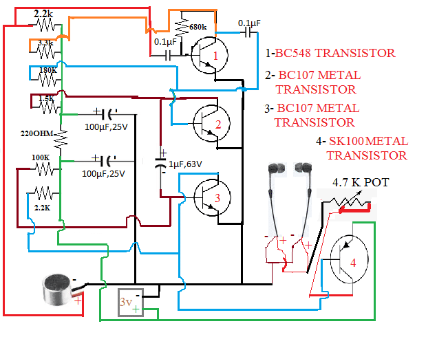
Ultra-High Fidelity High Power Amplifier Reference Design; Speach Amplifier; DC-Coupled Audio Amplifier; A Low Power Wireless Audio Power Amplifier; Here is an inexpensive hearing aid circuit that uses just four transistors and a few passive components. Circuit diagram. Parts: R1 = 2.2K R2 = 680K R3 = 3.3k R4 = 220K R5 = 1.5K

By using capacitor C7, it lowers the gain in the high-frequency band.T to keep the circuit stable while reducing noise, Headphones are directly linked to the power supply and get the audio signal from the collector. Thus, the headphone is a load of this circuit. Application Uses. Hearing aid devices. With the right guidance and knowledge, you can take charge of your hearing health and create a device that works well for you. So, don't be afraid to dive in and explore the possibilities of hearing aid engineering! A Low Cost Hearing Aid Circuit Diagram. Speach Amplifier Circuit Diagram And Instructions.

Simple Hearing Aid Circuit using 1.5V Battery Circuit Diagram
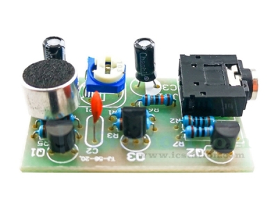
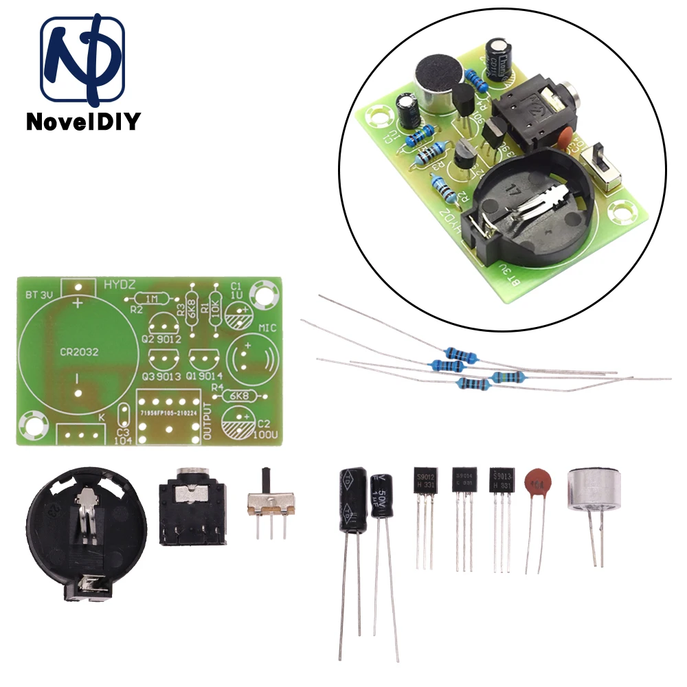
The LM386 is a low-voltage audio power amplifier IC that is perfect for this project. the external components used. The LM386 is easy to use and requires minimal external components, making it ideal for a simple hearing aid circuit. and a little bit of technical know-how, you can create a basic hearing aid that can help improve your or Low-cost hearing aid circuit. The circuit can be easily assembled on a small, general-purpose PCB or a Vero board. It operates off a 3V DC supply. For this, you may use two small 1.5V cells. Keep switch S to 'off' state when the circuit is not in use. To increase the sensitivity of the condenser microphone, house it inside a small tube.