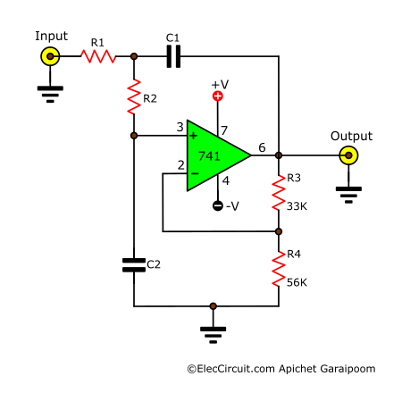
Low pass filter circuit 10KHz using uA741 Circuit Diagram Active Low pass filter can be used at multiple places where passive low pass filter cannot be used due to the limitation about gain or amplification procedure. Apart from that the active low pass filter can be used in following places:-Low pass filter is widely used circuit in electronics. Here are few applications of Active Low Pass Filter:-
The low pass filter calculator helps you design and build a low-pass filter circuit, with support for passive (RC and RL) as well as active (op-amp based) filters. RL low-pass filters. Active low-pass filters can be built with active components, most notably the operational amplifier (or op-amp). They include:

Low and High Pass Filters Circuit Diagram
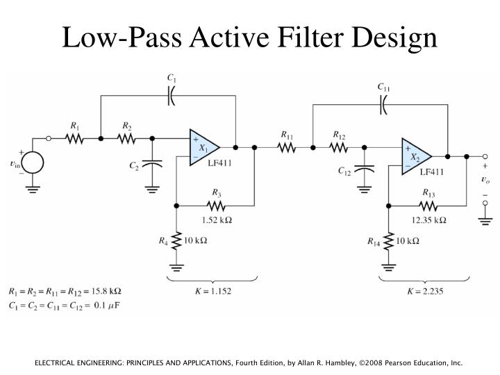
Active Low-Pass Filter Design Jim Karki AAP Precision Analog ABSTRACT This report focuses on active low-pass filter design using operational amplifiers. Low-pass filters are commonly used to implement anti-aliasing filters in data acquisition systems. Design of second-order filters is the main topic of consideration. To surmount this problem, active circuit designs were introduced. When a passive low pass filter is connected to an Op-Amp either in inverting or non-inverting condition, it gives an active low pass filter design. The connection of a simple RC circuit with a single Op-Amp is shown in the image below.. First Order Active Low Pass Filter with the frequency response
Active filters are circuits that use an op-erational amplifier (op amp) as the active device in combination with some resistors and Fundamentals of Low-Pass Filters Active Filter Design Techniques 16-7 16.2.2 Tschebyscheff Low-Pass Filters The Tschebyscheff low-pass filters provide an even higher gain rolloff above f C. However,
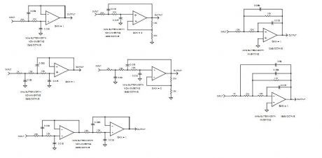
Active Low Pass Filter: Design and Applications Circuit Diagram
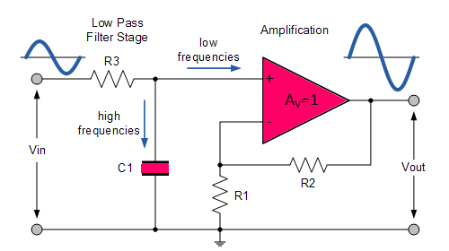
Active Low Pass Filter Circuit Diagram. The frequency response of Active low pass filter is same as that of the passive low pass filter, except that the amplitude of the output signals. The voltage gain of the non-inverting operational amplifier is given as. AF = 1+ (R2/R1) The gain of active low pass filter is given as By this action of the amplifier, the output signal will become wider or narrower. The maximum frequency response of the filter depends on the amplifier used in the circuit design. Active Low Pass Filter Circuit. The attenuation of the signal i.e. the amplitude of the output signal is lesser than amplitude of the input signal in the passive circuit.
Active Low Pass Filter Example No1. Design a non-inverting active low pass filter circuit that has a gain of ten at low frequencies, a high frequency cut-off or corner frequency of 159Hz and an input impedance of 10KΩ. The voltage gain of a non-inverting operational amplifier is given as: In an active low pass filter, the peak of the passband of the filter can be much larger than the input voltage signal because there is amplification. For passive low pass filters to be built, all that is required are resistors and capacitors. Active low pass filters require either transistors or op amps to provide amplification to the circuit.