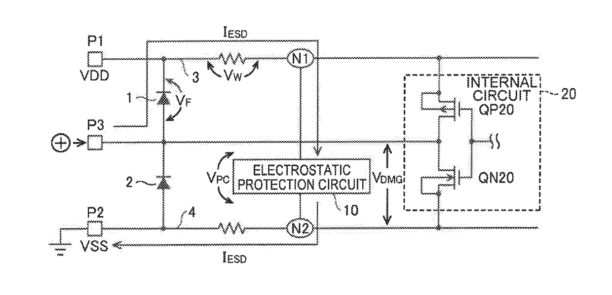
Circuit Protection Circuit Diagram Circuit protection refers to the comprehensive set of mechanisms and devices designed to safeguard electronic circuits from a wide range of potential threats. It acts as an impenetrable shield, shielding your circuits from overcurrent, voltage spikes, and various other electrical anomalies that can wreak havoc on your devices.

The protection of the circuit can be done by using different protection devices in an electrical circuit purposely in order to stop extreme amounts of current. To make sure extreme safety, this article gives an overview of circuit protection techniques , namely circuit breakers, ESD protection electronic fuses, gas discharge tubes, thyristors
Circuit Protection Design, Products & Methods Circuit Diagram
Key Components of a Protection Circuit. A protection circuit incorporates various components to effectively protect against overcurrent, short circuits, and overload current. 1. Circuit Breakers. Circuit breakers are the first line of defense in many protection circuits. They are automatic switches that can be triggered to interrupt the flow of
Many circuit protection techniques are often concerned with outside effects, but sometimes circuits need to be protected from themselves. One classic example of self-protection is short circuit protection with the use of a fuse.While not all circuits suffer from this problem, some designs may incorporate circuitry that has the potential to draw large amounts of current during fault conditions.

How to Choose the Right Protection for Your Circuit Circuit Diagram
With 1694 Electronic Circuit Protection the disconnection of the load happens electronically by a transistor. The trip characteristics of a 1694 Electronic Circuit Protector tolerates a momentary inrush current from e.g. switching on a capacitive load and limits the maximum current. In case of a current being too high for too long the 1694

Overvoltage Protection. A "crowbar" circuit (shown in Figure 1) can protect your device from overvoltage. In normal use, the 12V supply goes to the output via the reverse protection diode and fuse. The Zener diode is chosen to be slightly higher; in this case, 15V. When the input voltage reaches 15V, the Zener conducts, setting up a voltage across R2.