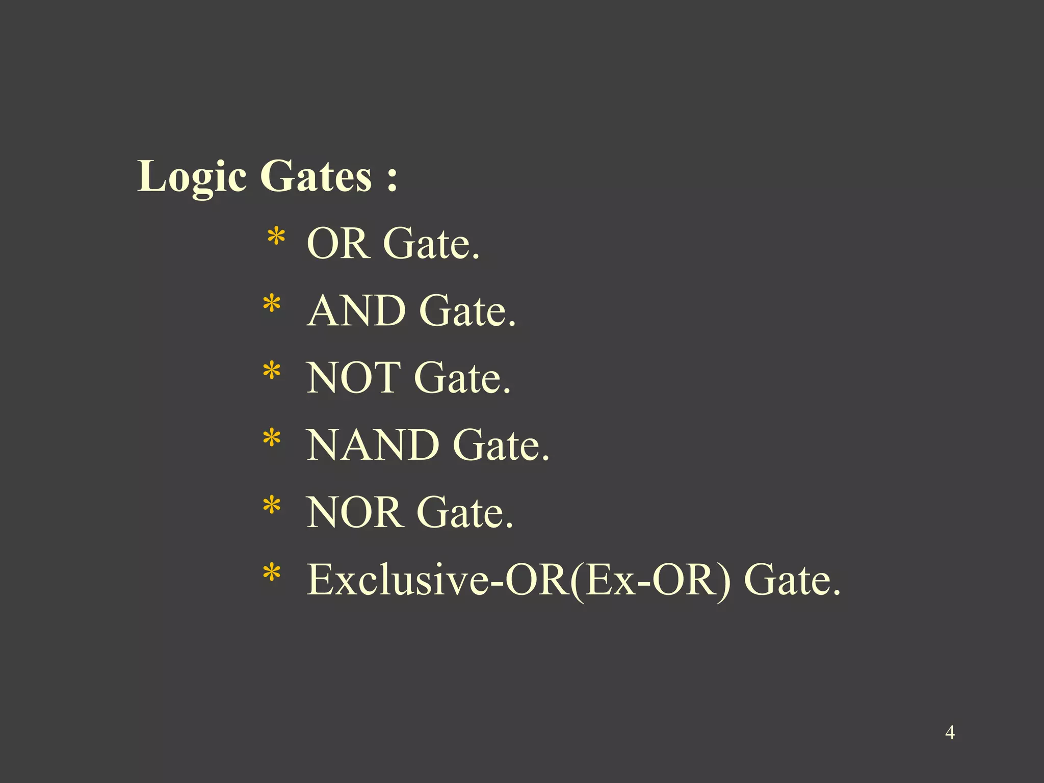
CEC 220 Digital Circuit Design PowerPoint Presentation free Circuit Diagram A digital circuit is a collection of interconnected digital components called gates.Gates have inputs and outputs.When Boolean signals (on or off) are applied to the inputs of a gate, the circuit produces a corresponding output depending on the type of the gate.The output of an and-gate is on if and only if both inputs are on.The output of an or-gate is on if and only if at least one of the
A digital logic circuit uses digital inputs to make logical decisions and produce digital outputs. Every logic circuit requires at least one input, before it can produce any kind of output. Digital logic inputs and outputs are usually binary. In other words they can only be one of two possible values.
LogicBlocks & Digital Logic Introduction Circuit Diagram
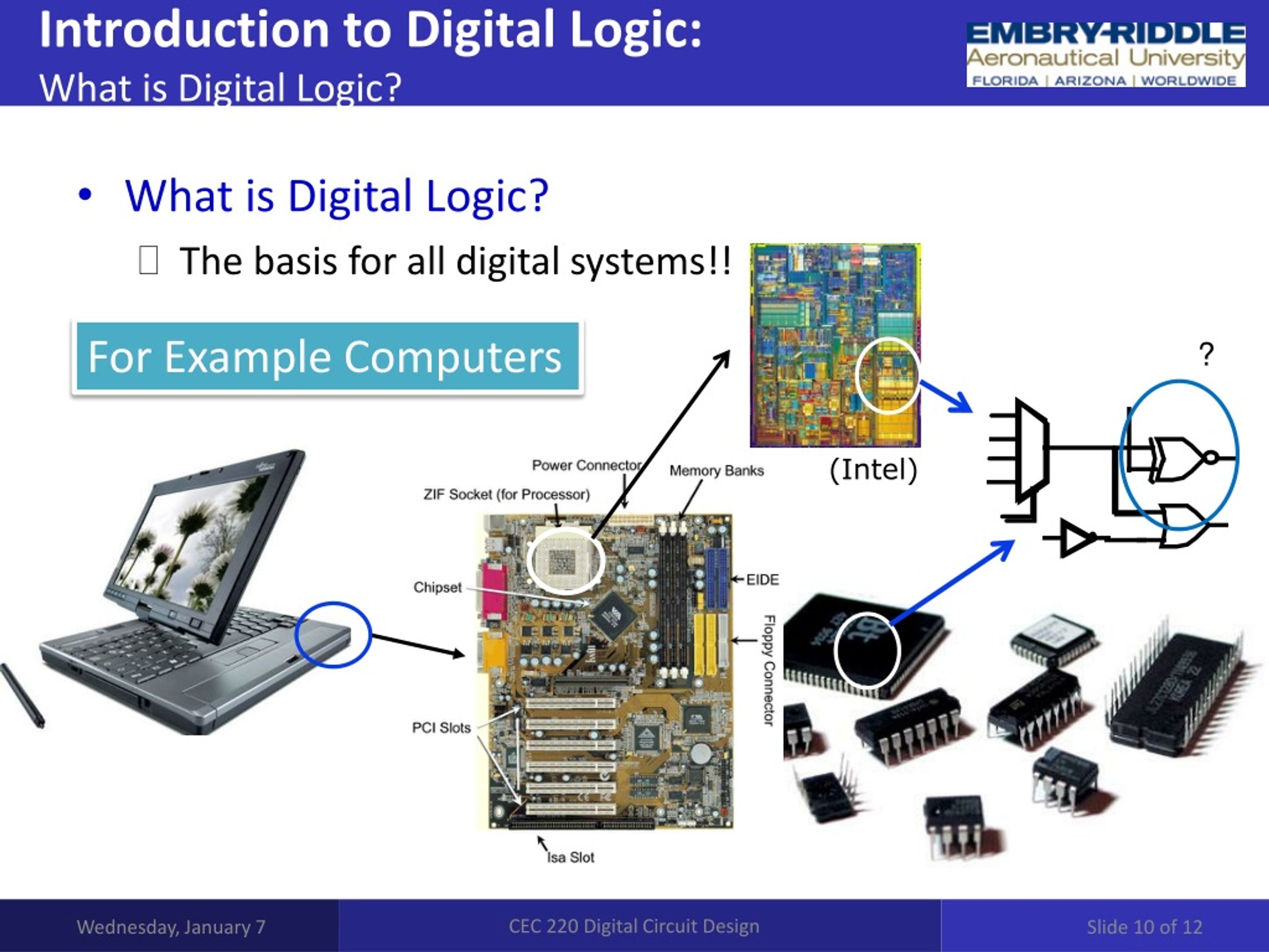
• Assemble a circuit. • Build a logic circuit with discrete components. The transistor A transistor is a three-terminal device that can be used as an amplifier or as a switch. When the transistor is used as an amplifier, it is working in analog mode. When it is being used as an electronic switch, it is functioning in digital mode. A half subtractor is a digital logic circuit that performs binary subtraction of two single-bit binary numbers. It has two inputs, A and B, and two outputs, DIFFERENCE and BORROW. The DIFFERENCE output is the difference between the two input bits, while the BORROW output indicates whether borrowing Lecture 1: Introduction to Digital Logic Design Syed M. Mahmud, Ph.D ECE Department Wayne State University •Semiconductor devices and circuits 9/4/2017 ECE 2610 - Digital Logic 1 2. Digital System •Digital age •Application of digital systems: •Communication, business transactions, traffic control, spacecraft guidance,

Introduction to Digital Logic Design CSE 140: Components and Design Techniques for Digital Systems . Winter 2016 . CK Cheng . Circuits Digital Circuits Logic Micro-architecture Architecture Operating Systems Application Software electrons transistors diodes amplifiers filters AND gates NOT gates adders

Introduction to Logic Circuit Diagram
This book is designed for use in an introductory course on digital logic design, typically offered in computer engineering, electrical engineering, computer science, and other related programs. Such a course is usually offered at the sophomore level. This book makes extensive use of animation to illustrate the flow of data within a digital system and to step through some of the procedures used